Skip header

Pulverized Coal Thermokinetic Properties Determination – the Drop Tube Test Facility

Coal burning plays an unsubstitutable part among primary energy resources in the Czech Republic. Especially by pulverized coal burning in power plants and heating plants we obtain a significant proportion of electricity and heat for our households and industry. However, these energy resources are out-of-date, therefore their renovation and building-up of new ones has been necessary. Modern power engineering has to meet high demands for efficiency, reliability, availability and, not least, also for minimization of impact of these large emission and waste sources operation upon our living environment. To meet these requirements, it is necessary, among others, to understand properly and to describe pulverized coal behavior during the combustion process in large-scale boilers and to make the best of these observations when designing new coal boilers.

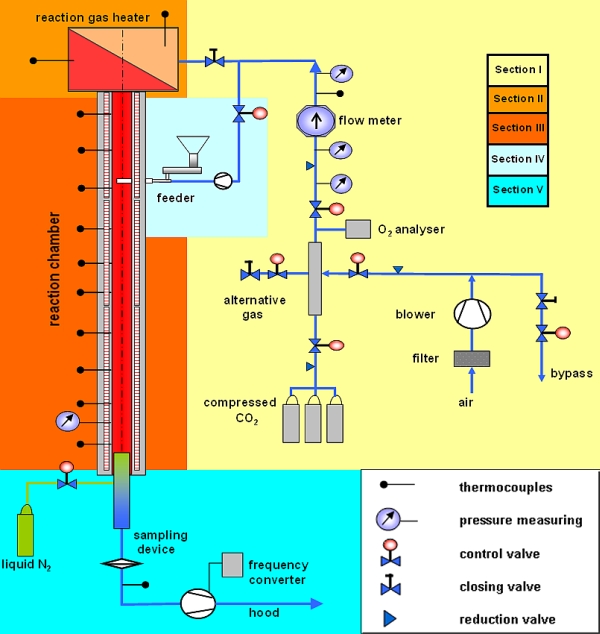
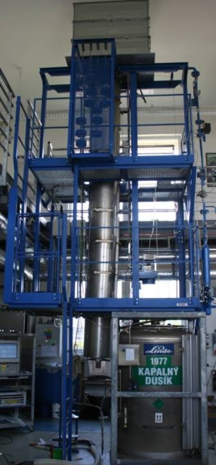
For this purpose, 1M 06059 project “Advanced Technologies and Systems for Power Engineering“ within „The Research Centres“ program of the Ministry of Education, Youth and Sports has been developed within the framework of which an experimental facility for pulverized coal thermokinetic properties determination has been built in the Energy Research Center’s testing laboratory. These properties are characterized by activation energy kinetic parameters and a pre-exponential factor and, in particular, by coal particles burnout progress. This experimental facility, the so-called drop tube, allows simulation of environment corresponding to conditions in large-scale pulverized-coal-fired boilers by setting-up temperature, oxygen concentration and reaction gas flow velocity in a reaction chamber. Gas parameters are set and controlled in a fully automatic mode.

Subsection for Nonspecialists

We take a small amount of pulverized coal and pour it at various height levels into the tube in which hot gas of given composition flows. Coal is dropping down and burning gradually. At the outlet from the tube, the coal and ash particles are caught on a filter and then analyzed which reveals this coal behavior when burning in a boiler.

Pádová trubka

Drop Tube Parameters

  1. Oxygen concentration in reaction gas – 0–21 %vol., N2 and CO2 concentration varies depending on oxygen concentration.
  2. Reaction gas temperature in the reaction chamber – 600 °C up to 1,200 °C.
  3. Reaction gas flow velocity – 1–4 m.s-1.

Reaction gas of required amount and concentration of oxygen ranging from 0–21 % is generated by mixing air supplied into the mixing part with the help of a blower and technical CO2 from a bundle of pressure cylinders, as shown in Fig. 2. The prepared gas flows through a reaction gas heater where electrical heating spirals are built-in (Fig. 10) which heat the gas up to 1,200 °C temperature. After heating up to the required temperature, gas enters the drop tube reaction chamber from above, and that by velocity within range of 1–4 m.s-1 in accordance with operator’s orders.

The reaction chamber (Fig. 11) is an electrically heated tube of 4,900 mm height and 66 mm inner diameter made of Kanthal APM (Fe75Cr20Al5), operational temperature up to 1,300 °C, resistant to oxidation environment. Regarding problems with the metal tube dilatation, heating modules are suspended on a counterweight (see Fig. 14). Eight batching holes with constant distance of 500 mm one from another are situated along the height. Sampling is performed with the help of sliding sampling probe cooled by liquid nitrogen onto an ash-less filter of 300 mm diameter (Fig. 12).

Sample Preparation

Preparation of a sample for testing consists of fuel sampling, drying, grinding and rough analysis and fixed carbon content determination (Fig. 4). Then the sample is sieved through sieves (meeting ISO and ASTM standards) to defined granulometry. Determination of particle size distribution is performed on the Mastersizer 2000 analyzer.

Experiment Description

Continuous batching of a selected granulometry sample in amount of c. 5 g / 15 min test, which affects reaction environment minimally, is provided by a vibrating fuel feeder (Fig. 15). Afterwards, the sample is injected pneumatically by a water cooled batching probe in a parallel way with the reaction chamber axis into the reaction gas vertical flow in which its gradual burn-out occurs in dependence on the residence time in the reaction media and the set parameters of reaction gas. Residence time depends on flowing reaction gas velocity and a sample trajectory length along the reaction chamber height which can be adjusted with the aid of 8 batching holes and the sliding sampling probe. During “fall” of pulverized coal particles in the reaction gas carrying flow towards the sampling point the combustion process occurs which is ended immediately in the sampling point by liquid nitrogen injection of boiling point –196 °C.

The captured sample is analyzed by determination of U unburned carbon (unburned carbon amount). Out of the unburned carbon determination result, the coal particles burnout curves in time intervals serving for set-up of the drop tube mathematical model can be accomplished.

Mathematical Model

On the basis of the real experimental facility, a mathematical model for coal particles burning-out in the drop tube has been defined in the ANSYS Fluent 12.0 program which serves not only for specification of the combustion process actual kinetic constants but, thanks to it, we can shorten time for determining a whole set of kinetic parameters for the given coal, thereby reduce purchase cost. The program is based on the finite volume method where a computational field (the drop tube in this case) is filled with finite elements (hexahedrons, tetrahedrons) in which numerical simulation of the mathematical model is performed (Fig. 6). Kinetic constants (Fig. 8) acquired on the basis of CFD simulation in the ANSYS Fluent 12.0 program can be then used for designing new pulverized-coal-fired large-scale boilers and also for designing the existing equipment reconstruction or for the combustion process optimization as shown e.g. in Fig. 15.