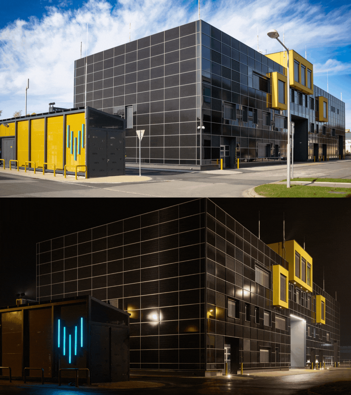
The laboratory is equipped with technological devices for the electrolytic production of hydrogen and equipment for its reconversion into electrical energy using fuel cells.
Fuel cells are used to produce direct current electrical energy and heat based on the direct conversion of gaseous fuel and an oxidant into electrical energy during a catalytic process supporting a non-explosive and non-flammable combination reaction. Pure gaseous hydrogen with defined purity and parameters will be used as fuel, and air will be used as the oxidant.
Fuel cell modules or "stacks" utilize chemical and physical processes corresponding to technology based on polymer proton membranes, and the individual fuel cell stacks will be structurally adapted for this technology. Installed in the laboratory are modules of low-temperature fuel cells, which, according to established international nomenclature, can be classified as "Proton Exchange Membrane Fuel Cells," commonly referred to as "PEM" or "PEMFC" fuel cells.
The Hydrogen Technologies Laboratory features designed distribution and measurement systems for technical gases to enable the connection of fuel cells with an installed capacity of approx. 100 kWe. The planned installation, serving for CEETe research purposes, consists of 5 modules ("stacks") in a primary series electrical connection, with a total installed output power of 50 kW, serving for the production of electricity (and heat) from the supplied gaseous hydrogen with specified parameters.
The electrical power is transferred via a coupling power converter—located in the control room of the hydrogen technologies laboratory—to the alternating current bus at a voltage level of 3 x 230/400 V, which is also intended for other CEETe technological units. The produced heat (up to 80 kWt) is dissipated primarily through a water cooling circuit with demineralized water, with a temperature gradient of 65/60 °C. This will be divided by a heat exchanger into two parts, with the secondary part already serving as part of the waste heat utilization system for the building's purposes.
The input media for the fuel cells will be:
- humidified reaction air (up to 5 x 500 Nl/min), supplied from the reaction air supply system by blowers (compressors),
- gaseous hydrogen (up to 5 x 200 Nl/min), stored in the area of the outdoor hydrogen filling station.
Inertization of the fuel cells will be performed using gaseous nitrogen.
Electrolyzers are used to produce gaseous hydrogen with defined parameters and quality according to the specification below. The electrolyzers are fundamentally based on the principle of electrolysis of water or a suitable aqueous electrolytic solution using solid ion polymer membrane technology. Distribution and measurement systems for technical gases are designed in the laboratory to enable the connection of two types of electrolyzers with a max. installed power input of 85 kWe.
AEM-type electrolyzers are installed in several free-standing modular carts. The produced gaseous hydrogen will be discharged from individual production blocks via separate pressure hoses in the required number corresponding to the equivalent of hydrogen production, i.e., 4 Nm³/block.
The operational hydrogen production by these electrolyzers is expected to be at least 1 Nm³/h (max. 8 Nm³/h) at an overpressure of 30 bar. A system for adjusting physical parameters of hydrogen—residual moisture separation—is integrated into the piping route for the discharge of the produced hydrogen. The medium (electrolyte) for hydrogen production is a solution of demineralized water with a 1% content of K₂CO₃ + KHCO₃.
The electrolyte circuit, which serves the dual purpose of cooling and supplying reaction water, will be automatically replenished during the operation of the AEM electrolyzers in the amount of 4 l/h for each production block, totaling up to 8 l/h. The electrolyte circuit ensures heat removal from the electrolyzer units with a value of 12 kWt while maintaining a temperature gradient of 45/40 °C. In the supply branch of this circuit, located mostly one floor higher (HVAC machine room), a heat exchanger will be connected to the central CEETe cooling water source. The return branch (from the electrolyzer outlet), containing not only the electrolyte but also gaseous oxygen produced by electrolysis in an amount of min. 2 Nm³/h (max. 4 Nm³/h), will be routed into an unpressurized expansion tank. From there, the accumulated oxygen, together with the water mist forming in the tank, will be actively ventilated outside the building by a fan. An electric heater will also be installed in the tank for the electrolyzer start-up phase. Their inertization will be carried out using gaseous nitrogen.