Skip header

CEETe

Center of Energy and Environmental Technology – Explorer

The intention of CEETe – Center of Energy and Environmental Technology – explorer (hereinafter also referred to as "CEETe"), is part of the integrated CEET project. This is an ambitious applied research project focusing on energy technologies, the output of which is the creation of a unique testing facility for methods and technologies in modern energy, fully in line with the principles of the circular economy. From the very beginning, CEETe has been designed in close cooperation with potential recipients of the planned innovation infrastructure services to ensure it aligns with current trends and the needs of the application sphere, primarily from traditional industrial sectors such as energy, metallurgy, mechanical engineering, transport, ICT, and waste and water management.

The project name, Center of Energy and Environmental Technology – explorer, suggests the pioneering and mobile nature of the center. The main intent of the project is to install a unique combination of technologies and methods for the thermochemical conversion of alternative fuels, alongside methods for energy accumulation and distribution to ensure energy and raw material self-sufficiency. This includes the ability to find an immediate combination of the most suitable method for energy conversion and distribution, while simultaneously offering a modular, scalable "LEGO System". In addition to the traditional concept of providing innovation infrastructure services in the energy sector, it also incorporates water management. It utilizes alternative and renewable energy sources (e.g., photovoltaics, wind turbines, heat pumps, technologies for thermochemical energy conversion), while integrating the hydrogen economy into the energy conversion process. The processes are controlled by a sophisticated distributed control system.

The project is also unique in its origin. It builds on the expertise of all existing university research centers focused on energy, which allows it to set the ambitious goal of building the key infrastructure required for the demanding task of fundamentally transforming the energy economy.

CEETe Robot Assembly Instructions

Virtual tour

Research and Development for Sustainable Energy

Explore the modern laboratories and research facilities of our innovation testbed, showcasing the future of energy and environmental technologies as we move away from fossil fuels towards a more sustainable future.

News

CEET Workshop 2024 – Inspiration for the Future

The fourth annual workshop of the Centre for Energy and Environmental Technologies (CEET), held on December 9, 2024, at the Poklad Cultural House, introduced a completely new...

10. 12. 2024 News 9391 - CEET's secretary's office

The Opening Ceremony CEETe

Director of the Center for Energy and Environmental Technologies, Prof. Stanislav Mišák, Ph.D., cordially invites you to the grand opening of the new CEETe polygon, which will take...

8. 9. 2023 Events 9390 - Centre for Energy and Environmental Technologies

Laboratories

Energy Sources Laboratory

The battery storage system is equipped with bidirectional inverters with a capacity of 250 kVA. The nominal battery capacity is 540 kWh, designed to achieve a usable capacity of 486 kWh at a 90% Depth of Discharge (DoD).

PCS (Power Conversion System) Inverter:

It is a modular and bidirectional inverter that can be equipped with a maximum of 8 modules of 62.5 kW to achieve a nominal power of 500 kW. For the CEETe building, the inverter is equipped with 4 modules of 62.5 kW to achieve a nominal power of 250 kW.

The main features of the offered inverter (PCS) are:

  • Modular design and wide power range in a single switchboard cabinet
  • Bidirectional inverter function
  • "Grid-support" function
  • Multiple DC battery strings, various application options for battery mixes

Battery cells are grouped into battery packs. These are further grouped into a battery module. Together with the Battery Management System (BMS), these accumulators are mounted into a rack. Several racks form the Battery Energy Storage System (BESS).

The batteries in the laboratory have the following technical specifications:

  • 38.4 V 128 Ah battery modules (38.4 V 148 Ah) 1C discharge / minimum 5000 cycles at 50 °C, complete with the BMS and cabinet.
  • Operation with so-called Grid-forming inverters (unit approx. 50 kW)
  • Operating temperature: 0 to 50 °C
  • Rate: 1C for discharge (charging with an average of 6 hours using a solar photovoltaic power plant).
  • Cycles within lifespan: minimum 5000 full charge/discharge cycles at 50 °C
  • Efficiency: > 96%
  • Ambient humidity: up to 90%

Hydrogen Technologies Laboratory

The laboratory is equipped with technological devices for the electrolytic production of hydrogen and equipment for its reconversion into electrical energy using fuel cells.

Fuel cells are used to produce direct current electrical energy and heat based on the direct conversion of gaseous fuel and an oxidant into electrical energy during a catalytic process supporting a non-explosive and non-flammable combination reaction. Pure gaseous hydrogen with defined purity and parameters will be used as fuel, and air will be used as the oxidant.

Fuel cell modules or "stacks" utilize chemical and physical processes corresponding to technology based on polymer proton membranes, and the individual fuel cell stacks will be structurally adapted for this technology. Installed in the laboratory are modules of low-temperature fuel cells, which, according to established international nomenclature, can be classified as "Proton Exchange Membrane Fuel Cells," commonly referred to as "PEM" or "PEMFC" fuel cells.

The Hydrogen Technologies Laboratory features designed distribution and measurement systems for technical gases to enable the connection of fuel cells with an installed capacity of approx. 100 kWe. The planned installation, serving for CEETe research purposes, consists of 5 modules ("stacks") in a primary series electrical connection, with a total installed output power of 50 kW, serving for the production of electricity (and heat) from the supplied gaseous hydrogen with specified parameters.

The electrical power is transferred via a coupling power converter—located in the control room of the hydrogen technologies laboratory—to the alternating current bus at a voltage level of 3 x 230/400 V, which is also intended for other CEETe technological units. The produced heat (up to 80 kWt) is dissipated primarily through a water cooling circuit with demineralized water, with a temperature gradient of 65/60 °C. This will be divided by a heat exchanger into two parts, with the secondary part already serving as part of the waste heat utilization system for the building's purposes.

The input media for the fuel cells will be:

  • humidified reaction air (up to 5 x 500 Nl/min), supplied from the reaction air supply system by blowers (compressors),
  • gaseous hydrogen (up to 5 x 200 Nl/min), stored in the area of the outdoor hydrogen filling station.

Inertization of the fuel cells will be performed using gaseous nitrogen.

Electrolyzers are used to produce gaseous hydrogen with defined parameters and quality according to the specification below. The electrolyzers are fundamentally based on the principle of electrolysis of water or a suitable aqueous electrolytic solution using solid ion polymer membrane technology. Distribution and measurement systems for technical gases are designed in the laboratory to enable the connection of two types of electrolyzers with a max. installed power input of 85 kWe.

AEM-type electrolyzers are installed in several free-standing modular carts. The produced gaseous hydrogen will be discharged from individual production blocks via separate pressure hoses in the required number corresponding to the equivalent of hydrogen production, i.e., 4 Nm³/block.

The operational hydrogen production by these electrolyzers is expected to be at least 1 Nm³/h (max. 8 Nm³/h) at an overpressure of 30 bar. A system for adjusting physical parameters of hydrogen—residual moisture separation—is integrated into the piping route for the discharge of the produced hydrogen. The medium (electrolyte) for hydrogen production is a solution of demineralized water with a 1% content of K₂CO₃ + KHCO₃.

The electrolyte circuit, which serves the dual purpose of cooling and supplying reaction water, will be automatically replenished during the operation of the AEM electrolyzers in the amount of 4 l/h for each production block, totaling up to 8 l/h. The electrolyte circuit ensures heat removal from the electrolyzer units with a value of 12 kWt while maintaining a temperature gradient of 45/40 °C. In the supply branch of this circuit, located mostly one floor higher (HVAC machine room), a heat exchanger will be connected to the central CEETe cooling water source. The return branch (from the electrolyzer outlet), containing not only the electrolyte but also gaseous oxygen produced by electrolysis in an amount of min. 2 Nm³/h (max. 4 Nm³/h), will be routed into an unpressurized expansion tank. From there, the accumulated oxygen, together with the water mist forming in the tank, will be actively ventilated outside the building by a fan. An electric heater will also be installed in the tank for the electrolyzer start-up phase. Their inertization will be carried out using gaseous nitrogen.

Thermochemical Conversion Laboratory

Generally, plasma gasification technology is cleaner and more environmentally friendly than conventional gasification or combustion processes. Plasma gasification is based on a thermal process in which waste (or other input feedstock) is exposed to the extreme thermal conditions prevailing in the plasma, reaching temperatures of up to 2,000 °C.

Overall, the plasma gasification process consists of several steps, including suitable pretreatment and dosing of input raw materials into the plasma gasification reactor, the gasification reactor itself, syngas cleaning (or separation of its components of interest), and the final utilization of the energy gas. This gas can be used, for example, for the production of synthetic fuels via Fischer-Tropsch synthesis, for electricity and heat production in a cogeneration unit, or for hydrogen production, which, after thorough purification, can be further utilized in fuel cells.

As previously mentioned, a device called a plasma torch or plasmatron is used to generate thermal plasma in plasma gasification. Currently, the laboratory is equipped with a plasmatron featuring a total power of 150 kW and the necessary support system for its operation. The plasmatron laboratory equipment includes a superheated steam generator, a cooling circuit, a fuel conveyor, an oxidizing medium supply, a waste system, high-temperature filtration equipment, wet and alkaline gas scrubbing equipment, separation membrane technology, and more.

Building energy management

Supplier: Schneider Electric
Type: EcoStruxure™ Microgrid Advisor (EMA)

Features

  • Reduction of energy costs, carbon footprint reduction
  • Ensuring the reliability of power supply from local generation facilities
  • Standalone operation, black start
  • Seamless grid – island – grid transitions
  • Voltage and frequency stabilization
  • Smoothing of renewable energy sources or loads
  • Peak load management (peak shaving)

Photovoltaic systems

  • Orientation: East, South, West
  • 5 inverters, manufacturer: Huawei Technologies, type: SUN2000-40KTL-M3
  • 1 inverter, manufacturer: Huawei Technologies, type: SUN2000-15KTL-M2
  • 1 inverter, manufacturer: Huawei Technologies, type: SUN2000-10KTL-M1
  • Optimizers installed throughout
  • Total number of panels: 473 pcs, Manufacturer: JA Solar Holdings Co., Ltd., type: JAM60S21-370/MR
  • Panel area: 883.7 m²
  • Estimated specific annual energy yield: 516.3 kWh/kWp
  • Estimated annual production: 90.505 MWh

Battery storage

  • Capacity: 500 kWh
  • Manufacturer: Pylontech
  • Inverter power: 250 kVA
  • Manufacturer: Schneider Electric

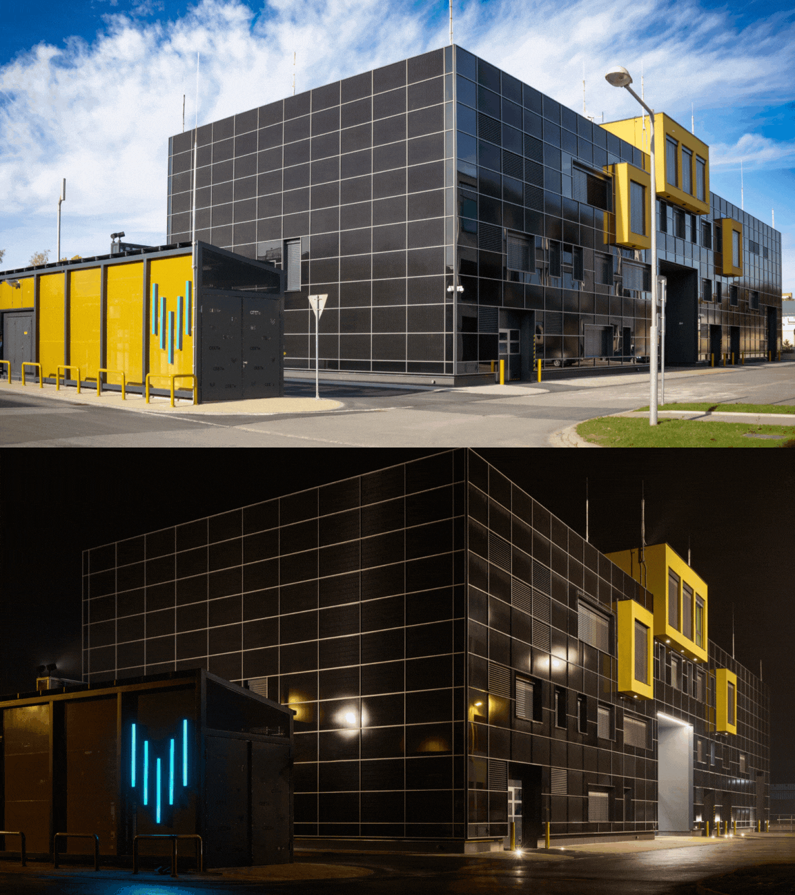
Budova_Den_Noc

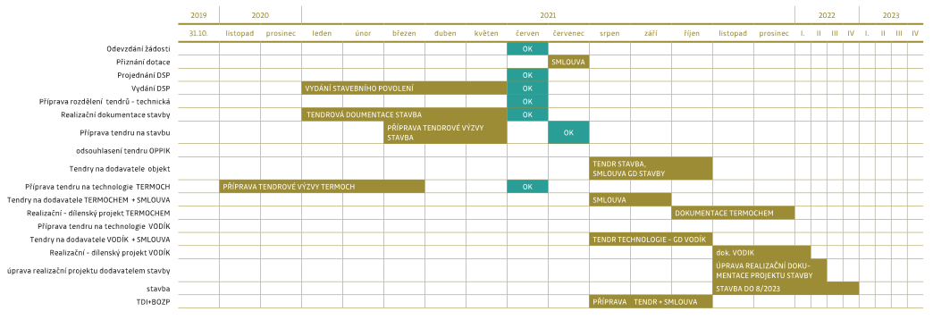
Project implementation schedule

Project start and end dates, phasing, description of individual stages

The project implementation schedule was developed in cooperation with all involved professions; therefore, it should be feasible and no major changes should occur. Individual activities are planned with time buffers so that change management procedures do not need to be initiated in the event of minor delays. The project is divided into stages, with three stages anticipated. The estimated start of the project implementation is November 30, 2020, the estimated start of the physical implementation of the project is September 1, 2021, and the estimated end of the project implementation is September 30, 2023, after which the final report will be prepared and the final payment request submitted.

CEETe_schema

The project Centre for Energy and Environmental Technologies – Explorer is co-financed by the European Union.

EU

The CEETe project was co-financed from the budget of the Moravian-Silesian Region.

MSK